Fujikura 70S Fusion Splicer
The Fujikura 70S fusion splicer is the fastest fusion splicer in the world. Tovább »
| ATL Zrt. | |
| Headquarters: | 2011 Budakalász Csapás u. 12. |
| Location: | 2011 Budakalász Káplán u. 1. |
| Telephone: | +36 26 560 344 |
| E-mail: | info.hu@atl-fo.eu |
| Headquarters: | ATL Electronic Srl. Ro-450031 Zalau Str. 22 Decembrie 1989 Nr. 67. |
| Location: | ATL Electronic Srl. Ro-450031 Zalau Str. 22 Decembrie 1989 Nr. 91/A. |
| Telephone: | +40 260 610 144 |
| E-mail: | info.ro@atl-fo.eu |

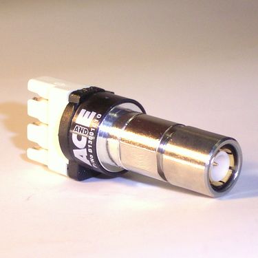
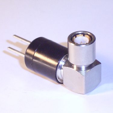
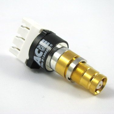
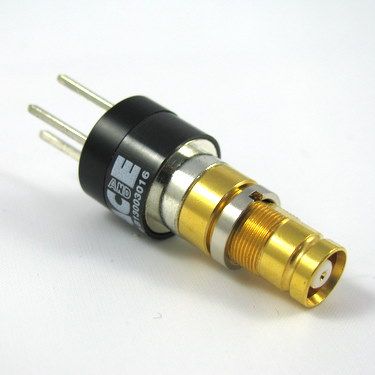
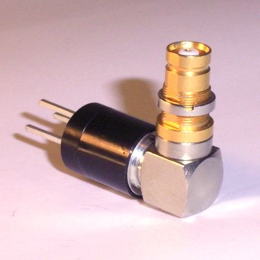
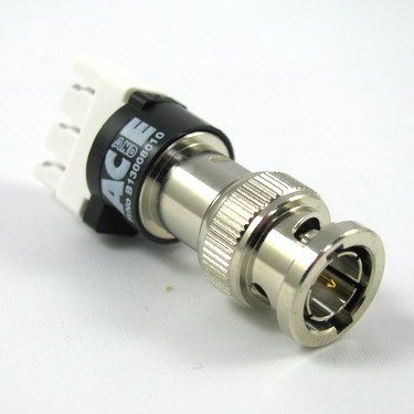
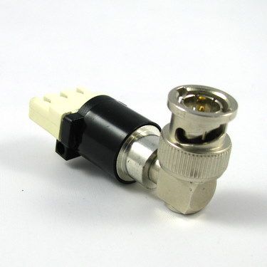
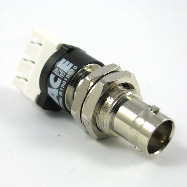
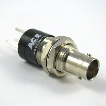
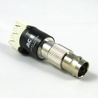
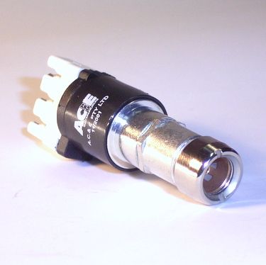
(Identify by black coloured outer body insulation ring)
Electrical Characteristics and Performance:
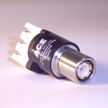
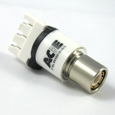
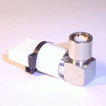
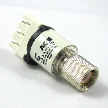
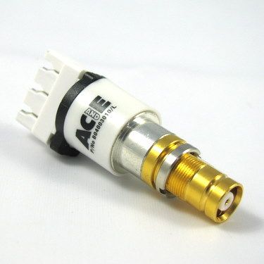
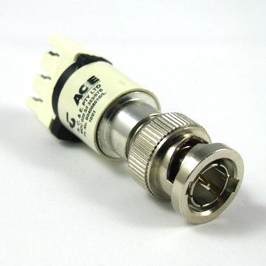
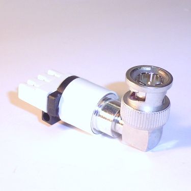
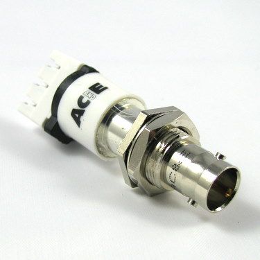
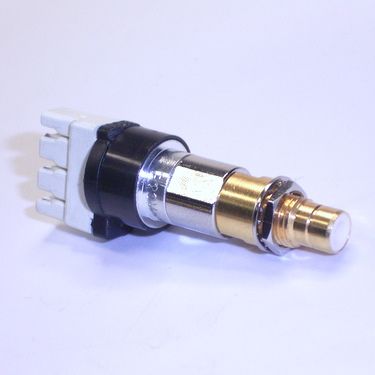
Identifiable by its outer body insulating ring which is coloured white.
Electrical characteristics and performance
BALUN is a word derived from terms applied to BALanced to UNbalanced transmission lines, and generally refers to an impedance matching device for interfacing two lines having different characteristic impedance and often one balanced line to one unbalanced line. (There are devices called UNUN’s, they are unbalanced to unbalanced devices.)
The balanced lines normally refer to twisted pair cables and the unbalanced lines to coaxial cables due to the way the cables are designed. The balun device generally consists of a radio frequency transformer having two windings matching the respective impedance of the lines. Often tuned to provide optimum matching, maximum return loss, minimum insertion loss and other frequency characteristics. Fitted with some type of connecting terminals for the balanced twisted pair end and a coaxial connector at the unbalanced coaxial end. Sometimes they also include voltage surge suppression components.
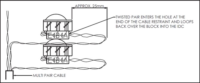
1. Mount the balun to the panel (if applicable).
2. Strip the cable sheath to expose the individual twisted pairs (if applicable)
3. Pass the desired twisted pair through the cable restraint hole in the moulding entering at ’A‘
4. Loop the wires back over and into the appropriate slot in the IDC connector.
5. The IDC marked ’A‘ corresponds with the centre contact in the coax connector, ’B‘ corresponds to the outer contact and ‘E’ earth.
6. Terminate the IDC using a Krone terminating tool.
7. Dress the cables as shown in the diagram below, allowing a loop of about 25mm at the cable entry in case the wires need to be re-terminated.
Black Balun Order Codes
| Part No | Description |
| B04 001 010/N | 1.6/5.6 (m) snap to 3 pole Krone IDC |
| B13 002 010 | 1.6/5.6 (m) screw to 3 pole Krone IDC |
| B13 003 010 | 1.6/5.6 (f) to 3 pole Krone IDC |
| B04 025 010/N | 1.6/5.6 (m) Rt. angle snap to 3 pole Krone IDC |
| B13 008 010 | BNC (m) to 3 pole Krone IDC |
| B04 009 010 | BNC (f) to 3 pole Krone IDC |
| B04 028 010 | BNC (m) Rt. angle to 3 pole Krone IDC |
| B13 019 010 | BNC (f) bulkhead to 3 pole Krone IDC |
2-8-34Mbit/s Standard Balun Order Codes
| Part No | Description |
| B04 001 010/L | 1.6/5.6 (m) snap to 3 pole Krone IDC |
| B04 002 010/L | 1.6/5.6 (m) screw to 3 pole Krone IDC |
| B04 003 010/L | 1.6/5.6 (f) to 3 pole Krone IDC |
| B04 025 010/L | 1.6/5.6 (m) Rt. angle snap to 3 pole Krone IDC |
| B04 008 010/L | BNC (m) to 3 pole Krone IDC |
| B04 009 010/L | BNC (f) In-line to 3 pole Krone IDC |
| B04 028 010/L | BNC (m) Rt. angle to 3 pole Krone IDC |
| B04 019 010/L | BNC (f) bulkhead to 3 pole Krone IDC |


