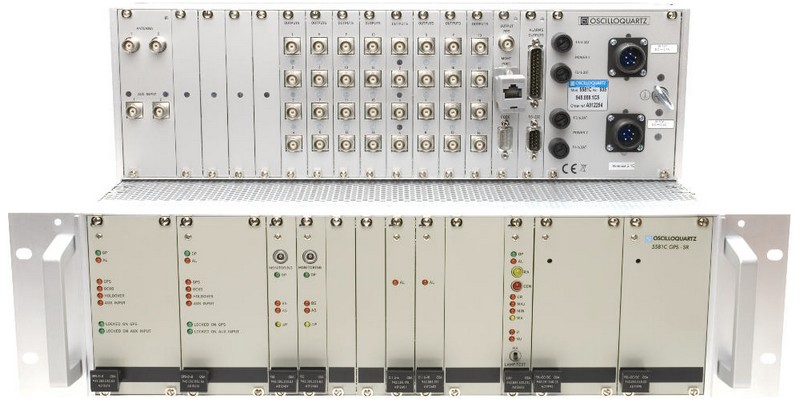
OSA 5581C GPS-SR
G.811/Stratum 1 Synchronisation Reference Source for SDH/SONET and Mobile Networks
Features
Flexible, modular, fully redundant synchronisation solution for fixed (SDH/SONET) and mobile (TDMA, CDMA, GSM, 3rd generation) telecom networks
- Fully redundant GPS receiver + sync distributor in a single box
- Highly modular: allows to build low-cost, non-redundant, few-output configurations
- Highly flexible: up to 64 outputs or up to 24 re-timing channels or a combination of both
- Highly versatile: optional module for Stratum 1 NTP server
- Highly reliable: no single point of failure, hitless switching in case of faults
- ITU-T G.811 Reference when locked to GPS
- ITU-T G.812 Reference when locked on auxiliary input or when in holdover
- Fully manageable, both locally (RS-232) and remotely (10BaseT Ethernet) via OSA synchronisation management software.
- High quality holdover capability: Compliant to G.812 (I,II, V, VI) SSU / GR-1244-CORE Stratum 2
- Input signals: Up to two GPS modules with two external sync inputs.
- Re-timing function: Re-timing of both El and T1 traffic carrying signals.
- Output signals: 2.048Mbit/s (E1), 1.544 Mbit/s (T1), 64/8 Kbit/s Composite Clock, 2.048/5/10 MHz.
- Output protection: protected (1:1) and unprotected mode.
- Time code outputs: Network Time Protocol NTP.
- Output connectors: Wide choice of connectors in both balanced and unbalanced configuration.
- NEBS level 3 certified
Applications
There are many applications for the OSA 5581C GPS:
- It is ideal as a low cost ITU-T G.811 Primary Reference Clock / GR-2830-CORE Stratum 1.
- Its excellent internal oscillators attenuate the GPS-specific jitter & wander and deliver a frequency signal which meets ITU-T G.811 / GR-2830-CORE, even under harsh temperature conditions.
- A GPS receiver that is used as the central PRC of an SDH- or SONET-based synchronisation network is required to have a high availability. Dual GPS receiver configuration is the appropriate solution for this application.
- OSA 5581C GPS can also be used as a telecom node clock to synchronise networks based primarily on GPS as a means to distribute synchronisation. Node clocks distribute synchronisation to all telecom equipment in their building or node, e.g. ADMs and DXCs in SDH or SONET network, digital switches, ATM switches. ITU-T G.811 / GR-2830-CORE performance is a prerequisite in nodes with international switches.
- A GPS-based synchronisation distribution does not require the same complex synchronisation distribution plan, as it is the case with conventional SDH- or SONET-based master/slave distribution. A distributed synchronisation plan architecture greatly simplifies the design and the maintenance of the synchronisation networks.
- Some telecom equipment also requires time-of-day information for e.g. billing and time-stamping. The OSA 5581C GPS provides all the necessary output time signals. The UTC-locked phase signal is useful in mobile networks, where base transceiver stations can be frame synchronised for better handover performances.
Telecom networks which are out of synchronisation often suffer from bit errors and slow transmission rates. Without precise timing, transmissions can lose some information during transport, particularly in the realm of optical transport data network and broadband systems.
As new standards emerge in the world of mobile telecommunications and digital broadcasting, the high quality of the synchronisation signal becomes increasingly important for cellular operators and media centres.
The OSA 5581C GPS is a GPS synchronisation receiver and distributor specially designed to eliminate these problems.
All critical parts in the OSA 5581C GPS, including the GPS input & holdover unit, can be duplicated to ensure high availability.
Technical Information
Input & Holdover
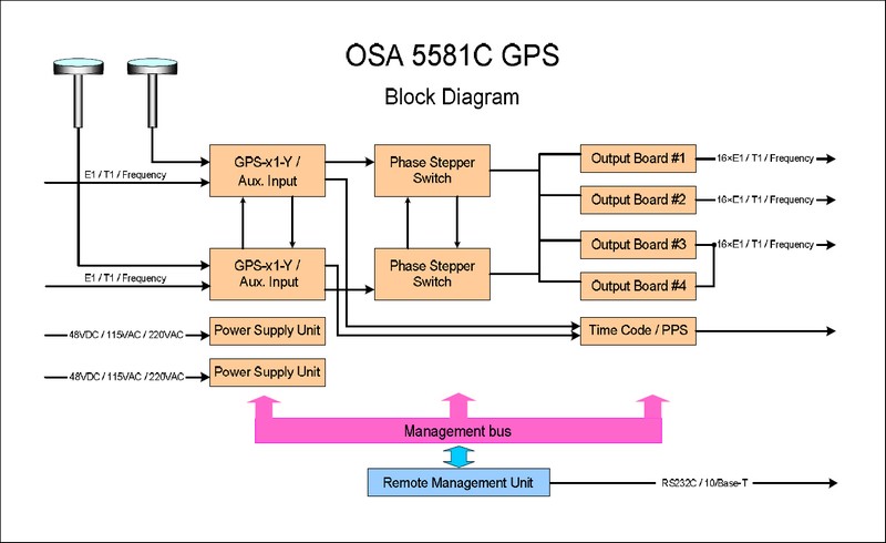
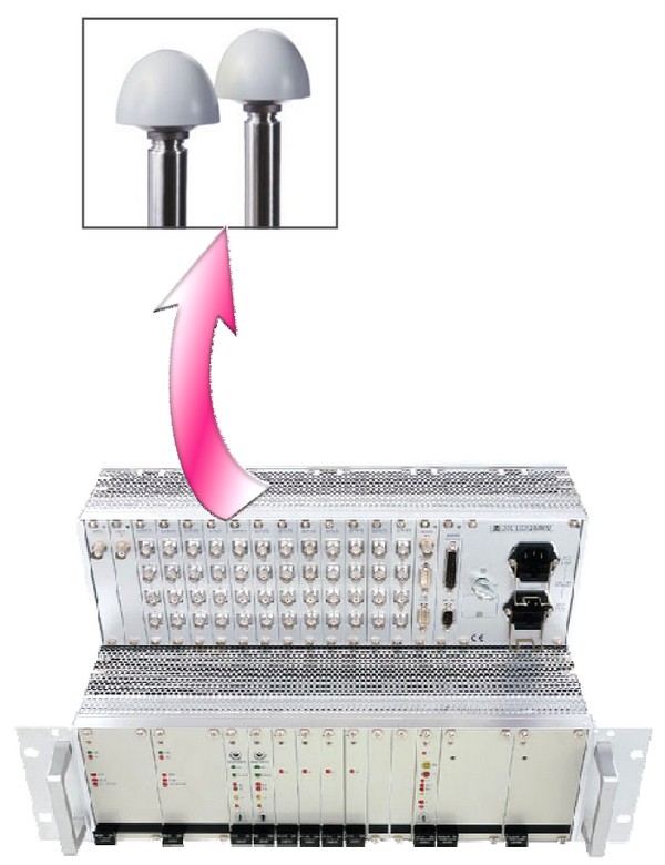
The OSA 5581C GPS can be equipped with dual redundant GPS input & holdover modules to provide unparalleled reliability. Each module features one GPS receiver and one auxiliary input reference accepting El or T1 signals or an auto detected frequency (1.544, 2.048, 5 or 10 MHz).
Thanks to its modularity, the equipment can also be configured with only one GPS input & holdover module for extremely low cost applications; upgrading to a fully-redundant dual channel solution at a later stage is made possible by simply inserting the necessary modules in their slots.
In cases where all GPS signals and external sync inputs are lost, the internal oscillator goes into holdover mode so as to then deliver both frequency and time-of-day information autonomously.
In holdover mode, the frequency output shows a frequency drift better than 1x10e-10 / day (OCXO) or 5x10e-11 / month (Rb).
Output & Re-timing
Besides being a top-quality GPS receiver with holdover capability, the OSA 5581C GPS provides also, in the same box, synchronisation distribution and/or re-timing, avoiding the need for separate equipment (and additional management connections).
It can provide up to 64 output synchronisation signals of telecom formats (E1, T1, and/or various frequencies), up to 24 E1/T1 re-timing channels or a combination of outputs and re-timing.
Time Code
Finally, the OSA 5581C GPS can be fitted with an NTP module to obtain a Stratum 1 NTP server providing accurate, GPS referenced time information on IP networks, and further taking advantage of the existing dual redundant GPS reference.
To add NTP functionality you just have to fit an NTP module in your OSA 5581C GPS: compare this elegant approach with the burden of installing another separate GPS receiver with its expensive GPS antenna and cabling; moreover, you also benefit of a high quality oscillator in case of GPS failure.
Besides NTP, other timing protocols can be made available on request.
Management
The OSA 5581C GPS is manageable in three different ways:
- Locally, through the RS-232 port and via the OSA Local Manager for 5581C, a graphical, intuitive, windows-based application
- Remotely, through the RS-232 port and modem connection, by using the same Local Manager coupled with the OSA Remote Access Manager software
- Remotely, through TCP/IP connection to the network management centre, by using Oscilloquartz' professional Management System SyncView
TECHNICAL SPECIFICATIONS
Physical dimensions
|
Re-timingRetiming of up to 24 traffic-carrying E1/T1 signals. |
PowerUp to 2 power supplies in any combination of:
|
Input
|
Time-code output
|
Oscillators, GPS input and holdover module
|
Antenna cables
|
Performance when locked to GPS signal
|
Output signals
|
Holdover performance
|
Management:
|
1. For certain types of connectors, max no of outputs is 48.
2. E1 output cards cannot be mixed with T1 or CC output cards in the same equipment
